Denavit-Hartenberg is a bookkeeping trick. A general transform between two frames needs six numbers; DH gets it down to four by refusing to place frames arbitrarily. You give up freedom in where the axes go, and in exchange every joint is described by one row of a table.
Each row turns into one homogeneous transform, and the chain multiplies out:
The four parameters
Every parameter is measured between two consecutive frames, which is why each carries a double index :
- - distance along , from to
- - angle from to , as seen from
- - angle from to , as seen from
- - distance along , from to
Notice the pattern: the two length parameters and the two angle parameters pair up on the two axes. and are both measured on ; and are both measured on . If you can remember which axis a parameter lives on, you can reconstruct its definition.
Some course material writes the offset along as . It is the same quantity as here, and is the letter used in the transform matrix.
Reading the parameters off a figure
The definitions are geometric, so most entries are read, not computed. Four shortcuts cover almost every exam figure:
| You see | Parameter | Value |
|---|---|---|
| and intersect | ||
| and are parallel | ||
| and are perpendicular | ||
| the axes are not offset sideways |
The sign of comes from the right-hand rule about : point your right thumb along and the fingers curl from towards for a positive angle. Half the lost marks in this section are a correct magnitude with the wrong sign.
The other half are a wrong variable. For a revolute joint, is the joint variable and , , are fixed by the geometry. For a prismatic joint it swaps: is the variable and is fixed. Exactly one entry per row moves.
Worked example: a three-joint arm
A waist that rotates about the vertical, a shoulder, and an elbow - three revolute joints, so three rows and three variables .
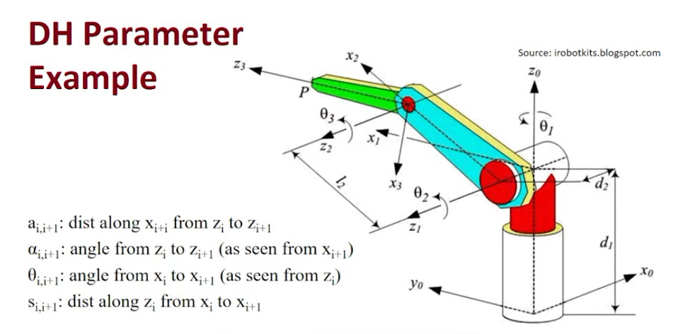
The arm the table below describes. Note the figure labels the fourth parameter s, which is the one written d here. Source: irobotkits.blogspot.com, via the course slides.
Work the frames left to right in the figure: up the base, and across the shoulder and elbow, out along the last link.
Frame assignment. points up the base column. The waist turns about it, so is the first joint axis. The shoulder axis is horizontal, perpendicular to . The elbow axis is parallel to , because the shoulder and elbow both swing the arm in the same vertical plane. runs along the last link.
Two constants come out of the figure: is the height of the base column, is the sideways offset from the base centre to the plane the arm swings in, and is the link length between shoulder and elbow.
| Joint | ||||
|---|---|---|---|---|
Row by row, the reasoning is the shortcut table above:
- Row 0 (base to shoulder). because the shoulder axis crosses the vertical base axis - no sideways gap to measure. because is vertical and is horizontal; they are perpendicular, and the sign follows from the right-hand rule about . is the waist rotation, the joint variable. is the climb up the base column, measured along .
- Row 1 (shoulder to elbow). : this is the only row with a real link length, because and are parallel and the common normal between them is the link itself. follows directly from that parallelism. is the lateral offset along .
- Row 2 (elbow to wrist). and : the axes intersect at the elbow with no offset, so frame 3 sits right at the joint. turns the axis back out of the arm’s plane to run along the final link - same magnitude as row 0, opposite sign, because it rotates the other way.
Two entries in this table are worth pausing on. First, only one row carries a link length; it is normal for most of the column to be zero when joint axes intersect. Second, the length of the last link never appears. The table stops at frame 3, and the tool point is described by a further fixed transform from frame 3 - it is not a joint, so it gets no row.
Assembling the result
Each row goes into the standard DH transform:
That matrix is not something to memorise. It is what you get when you apply the four parameters as four moves, in this order:
The order is not arbitrary. The two moves measured on come first, then the two measured on - the same pairing as the parameters themselves. Within a pair the order does not matter, because a rotation about an axis and a translation along that same axis commute. Between the pairs it matters a great deal.
The four elementary matrices
Every homogeneous transform is a rotation block with a translation column bolted on:
A pure rotation has ; a pure translation has . The four DH moves are the simplest possible cases of each:
You can write any of these from scratch in a few seconds with two rules:
- A rotation about an axis leaves that axis alone and puts a plain 2-D rotation in the other two coordinates. keeps row and column 3 as the identity and spins into ; keeps row and column 1 and spins into . The minus sign always sits above the diagonal, which is what makes the rotation right-handed.
- A translation is the identity with the distance in the last column, on the row of the axis you are moving along - row 3 for along , row 1 for along .
How the multiplication goes
One rule does all the work. For two homogeneous transforms:
Rotations just multiply. The second translation gets rotated by the first rotation before it is added on. Take the pairs one at a time:
Multiply those two and the rotation block is , which is the top-left of the DH matrix. The translation column is
which is the last column. That is the whole derivation.
Why only picks up the trig
Both and are plain distances in the table, so it is worth asking why the column comes out as and not .
Because the step happens after the rotation. By the time you step along , that axis has already been turned by , so the step lands at . The step is along , and a rotation about does not move - so passes through untouched.
The general version: anything measured on survives the rotation unchanged, and anything measured on arrives already rotated by it.
Why the moves multiply on the right
Each matrix is post-multiplied, which means every move is expressed in the frame the previous move just produced - not in the base frame. So you read the product left to right as a frame walking into place: start at frame , spin about its by , slide along that by , slide along the new by , spin about that by , and you have arrived at frame .
This is also why the chain telescopes:
Each factor is written in the frame the one before it produced, so the indices cancel through the middle and the last column of is the position of frame 3 in base coordinates. Had you pre-multiplied instead, every move would be measured in the fixed base frame and the product would not compose like this.
In practice
Substitute the numbers from the table before multiplying, never after. With the terms vanish and a whole column of the rotation block goes to zero; with the matrix drops to the planar case
and row 1 of the example arm, with , collapses just as hard. Multiplying three general symbolic matrices and substituting at the end is how these questions turn into an hour of algebra.
To invert one, never actually invert it - use the structure from 2.3: .
Sanity checks
- Set every joint variable to zero. The arm should fold into the home pose drawn in the figure, and should give the coordinates you can read straight off it.
- Each transform is still a rigid motion: the top-left block must stay orthonormal, so its columns are unit length and mutually perpendicular.
- Count the variables. Three revolute joints means exactly three symbols in the table and everything else a number or a fixed length.
The alternative
The product of exponentials does the same job without frame assignment - one screw axis per joint and its magnitude , with only a home configuration to fix:
DH is more compact once the table exists; PoE skips the intermediate frames, which is where DH errors come from. Exams ask for both, so the useful skill is recognising which description a question has handed you.